Given axis 1 on body 1 and axis 2 on body 2 that is perpendicular to axis 1 it keeps them perpendicular. Cross Universal Coupling GENERAL ASSEMBLY DRAWING DIMENSIONS AND STANDARD SIZES Size Model Rotary Diamet er D MM Nominal Torque Tn KNm Fatigue Torque Tf KNm Axial Angl e β D1 D2 D3 Lm n-d k t b g SWC100 100 16 08 25 84 57 60 55 06-Sep 7 25 - - SWC120 120 45 225 25 102 75 70 65 08-Nov 8 25 - -.

Machine Drawing Universal Coupling
The main application of the universal or hookes coupling is.
. It consists of a pair of hinges located close together oriented at 90 to each other connected by a. We additionally provide variant types and along with type of the books to browse. Keval Chaudhari-December 19 2015.
This video helps you to draw the assembled front and top view of universal coupling manuallyNow you can get all my drawings in PDF format AUTOCAD drawings. Keywords Universal Coupling CREO ANSYS Assembly Strain Stress INTRODUCTION In day-to-day life every aspect is influenced by the work of engineer. Home Tags Universal coupling assembly drawing pdf.
The flange coupling is designed as discussed below. These are the primary reasons for using Universal Joint Couplings. Universal Coupling Drawing 14 PDF Universal Coupling Drawing Machine DrawingIncludes Autocad-Singh 2008-12-07 This book is for the course on Machine Drawing studied by the undergraduate mechanical engineering students in their 3rd semester.
2 shows CAD design of a coupling. The hub is designed by considering it as a hollow shaft transmitting the same torque T as that of a solid shaft. Design for hub 1.
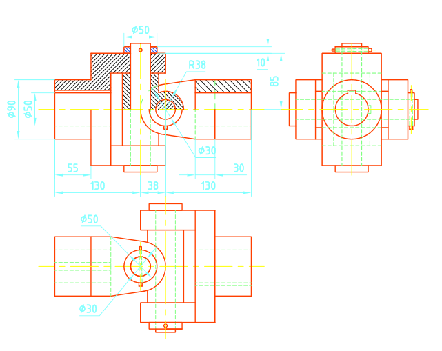
T π16 τc D4 d4 D The outer diameter of hub is usually taken as twice the diameter of shaft. UNIVERSAL COUPLING ASSEMBLY DRAWING1 v5pdf - 1 2 3 5 4 6 7 8 Parts List Item Part Number 1 1_Centre A A A B A-A Course Hero. The universal joint is not a constant velocity joint.
The main stress zone of a coupling is the yoke slot-hub interface and the hub corners. The tongue and groove on one side is perpendicular to the tongue and groove on the other. A universal or Hookes coupling is used to connect two shafts whose axes intersect at a small angle.
A colour monitor with highest 32 bit colour display and with screen resolution 1024 by 768 pixels. This is just one of the solutions for you to be successful. There are some available literature on universal coupling3.
June 3 2015 29 december 3 november 2 Fusion 360 rendering march 8th 2021 assembly modelling of uni. Your Universal Joint Coupling. In the yoke slothub interface the -.
Windows XP operating system 2. The main application of the universal or Hookes coupling is found in the transmission. And here you will get some Oldhams Coupling Assembly.
The equipments we use the food we eat and the. The middle disc rotates around its center at the same speed as the input and output shafts. CPU with pentium IV processor.
CAUSES OF ACCIDEENTS The accidents may take place due to human causes environmental causes and mechanical causes. Universal or Hookes Coupling. Universal coupling drawing pdf.
These causes are discussed as. Universal or Hookes Coupling. View UNIVERSAL COUPLING ASSEMBLY DRAWING1 v5pdf from MECH MEE1002 at Vellore Institute of Technology.
Analysis of universal coupling with the help of ANSYS for different torque or load condition and it verify by manual calculation. The ability to change length and angle during rotation under torque load further. 1 2 3 5 4 6 7 8 Parts List Item Part Number 1 1_Centre A A A B A-A.
Machine Drawing - Bearing- Universal Coupling - SGunabalan Associate Professor Mechanical Department Bharathiyar College of Engineering Technology Karaikal - 609 609. It consists of a cross. Up to 24 cash back To create the universal coupling assembly as a 3D solid model using CATIA V5 software.
A universal joint is like a ball and socket joint that constrains an extra degree of rotational freedom. Associate Professor at Bharathiyar College of Engineering and Technology Karaikkal. CATIA V5 PROCEDURE 1.
Universal Coupling Drawing Pdf. An Oldham coupling has three discs one coupled to the input one coupled to the output and a middle disc that is joined to the first two by tongue and groove. The novelty of the present literature is that it gives emphasis on yoke and hub separately.
A universal joint universal coupling U-joint Cardan joint Hardy-Spicer joint or Hookes joint is a joint or coupling that allows the shafts to bend in any direction and is commonly used in shafts that transmit rotary motion. Universal Joint Couplings offer a great deal of flexibility in the alignment of driving and driven units. Vailable universal coupling and Fig.
The inclination of the two shafts may be constant but in actual practice it varies when the motion is transmitted from one shaft to another. They transmit torque through an angle and provide long life. Universal or Hookes Coupling.
Attain you take that you require to get those every. Universal coupling assembly drawing pdf. TYPES OF COMMON TIMBERS THEIR QUALITIES.
9 28 A simple brief about Universal Coupling.
Machine Drawing Universal Coupling

03 Universal Coupling

36 Universal Coupling Final Pdf Computer Aided Design Technical Drawing

03 Universal Coupling

36 Universal Coupling Final Pdf Computer Aided Design Technical Drawing

Machine Drawing Universal Coupling

Universal Coupling Mechanical Engineering

Universal Joint Download Free 3d Model By Hirday2000 Cad Crowd
0 comments
Post a Comment